
Piezoelectric Step Based Power Generator
- Jason Li
- Nov 3, 2021
- 6 min read

Updated: Jan 15, 2022
August 2021 - December 2021
In our Product and Experimental Design class we were tasked with addressing a problem in the world. We decided that the problem we wanted to solve was:
How can we help university students charge their electronic devices without impeding normal day-to-day functions?
BRAINSTORMING
This problem was determined because:
Students need electronics for most of their classes this day and age, and there is not always access to outlets in classrooms
If power goes out, there needs to be a method to charge electronic devices
A new method for producing clean energy that most people could utilize
Multiple methods of charging
Assumptions:
Clean method of producing energy that can be done by most people
Compatible with most electronic devices (i.e. phones, laptops, watches, calculators)
Market size: 50% of University Students
Primary Market: University Students
Secondary Market: Military, hikers, workers in rural areas
A few problems we encountered at the start was:
How would we generate the power?
How much power would our device be able to store?
How could we make our product compact, lightweight, sturdy, and weatherproof?
How efficient could we make our device?
How could we make this device cost efficient?
How could we make this product safe?
What similar products are already out there?
The most important customer needs we determined was:
Generates power (Watt/hours, mAh)
Marginal: generates a detectable amount of power, stores 6000mAh
Ideal: generates enough power to effectively charge a device, stores 10000mAh
Cost (Dollars)
Marginal: only %15 above the average cost of a portable battery (about $40)
Ideal: Near the average cost of a portable battery (about $20-$30)
Weight (lbs)
Marginal: 25% heavier than average shoe (0.625 lbs)
Ideal: 15% heavier than an average shoe (0.375 lbs)
Weatherproof rating(IP rating)
Marginal: IP33
Ideal: IP64
efficiency (Amps)
Marginal: 1A
Ideal: 2.5A
Durability (Lifespan (miles))
Marginal: 350-500 miles
Ideal: Forever!
Ideas we came up with:
Pressure charging system:
Utilizes a pressure based Piezoelectric, where when force is applied to the sensor, an electric current is generated on the surface of the crystal in the Piezoelectric. This sensor will be located on the bottom of the foot, so when the user walks, the pressure from the weight of the user onto the sensor will produce current. The current will be connected to a battery, which will charge over time as the user walks.

Movement based charging system:
Utilizes detection of movement to generate electricity. When there is movement, a magnet will be moved according to the movement. The magnet will move past coils of wire, wherewith the laws of inductance, an electrical current will be generated.

Heat based generation:
Uses thermoelectric generators that utilize heat flux(temperature differences) to generate electrical energy. This uses materials that have high electrical conductivity and low heat transfer. Materials with low thermal conductivity create a high temperature gradient therefore enabling generation of a high voltage. The material will be located at the bottom of the shoe and connected to a battery which gets charged whenever there is heat flux between the ground and the inner part of the shoes.

Vibration based generation:
The vibration based generation design utilizes vibration based piezoelectric sensors to produce power when the user produces a vibration. A great advantage to this design is its versatility as it can be used on shoes, bikes, skateboards and even scooters to produce electricity.

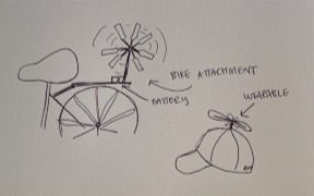
Wind based power generation:
A small turbine connected to a battery is attached to the user. When the person moves, there will be wind going through the turbine, causing the turbine to spin and generate electricity
Decision Matrix:

In our chart, we divided our selection criteria into six categories: Ease of use, Durability, Efficiency, Safety, Cost, and Ease of production. We then gave each category a different weight based on what we considered to be of greatest importance. The design concepts were evaluated based on a 1-5 scale of how well they fit the criteria of each category and those numbers were summed and weighting resulting in the final totals. After assessing these results, we selected the Pressure Charging System to work on as our solution. While the Movement Based System was a close second, the only component that ranked higher than the first was its waterproofing ability. Taking this into consideration, our group has decided to adapt our solution in order to fulfill this need.
DESIGN PHASE:
Block Diagram:
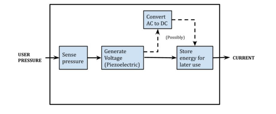
Input/Outputs:
Input: Pressure (from steps)
Output: Current (electricity)
Subfunctions:
Piezoelectric (critical)
Piezoelectric elements are placed under the major pressure points of each foot, which is then wired together to combine the voltage generated. The voltage generated is in AC form, which will then be harnessed and stored in the battery. The input of this subcomponent would be the pressure exerted by the user
Risk: Piezoelectric could very well not generate enough power to charge anything. One task we could accomplish this semester would be to run tests on what setup would generate the most power from piezoelectronics based on human walking mechanics
Step down converter(maybe)
If the voltage generated is not enough to charge a battery efficiently, a step up converter could be used after the voltage is converted from AC to DC. A DC to DC step up converter could make charging more effective if that was what is needed. On the flipside, since higher current should charge batteries faster, if we produce a higher voltage than needed, a step down converter could be utilized in the same was as the step up, instead to convert the DC voltage to a lower voltage with a higher current. The input and output of this subcomponent would be voltage/current.
Battery (critical)
Battery will store the electricity generated. This will either be located inside/outside the shoe. The battery will have a port whereby it enables someone to use it to charge a device(phone, watch, calculator…)
Risk: The electricity generated might not be enough to charge the battery
How to make sure that the battery weighs less at the same time being able to store enough electricity.
Circuit:
This is where the piezoelectronics are connected, and where the step up or step down will be wired. Ideally, a small circuit board will be located towards the back of the shoe, so the wires can be connected conveniently. The input of this subcomponent would the be power generated by the piezoelectronics, where the output would be the power after transformation into the battery
Risk: Major concern is how to make sure that the circuit does get damaged by water/any form of moisture. How to make sure that the circuit is water-resistant.
Frame:
The frame of our product is basically an insole, and the shoe itself. The piezoelectronics are housed inside the insole of the shoe, which would be wired to the circuit board, located in a separate 3d-printed component on the back of the shoe. The battery will also be attached to the user with the frame, providing easy access to charging
Risk: With our product very electronics focused, there is always the concern of humidity and water leakage for the frame. How could we make our design cost effective yet water-resistant? One task we could do this semester to adjust for this would be to do research on the best water-resistant materials and decide which material to use for our frame.
Gantt Chart:
PROTOTYPE PHASE:
Prototype 1:

To first make sure that our circuitry actually works, we set up a test circuit, diagram pictured to the left, actual circuit below

The circuits consisted of four piezoelectric sensors connected to a diode rectifier. This converts the AC current generated by the piezoelectric sensor into DC current (current that is able to be utilized by the portable battery). This is then connected to an open switch and a capacitor. This capacitor will be discharged once the switch is closed, and the right loop complete, lighting the LED up.
As the video in the right shows, our circuitry seems to work, so next was to design how to integrate this circuit into the shoe
Next steps after Prototype A:
We now had two major questions: where to place the sensors and how to wire electronics. We decided to place the sensors around the balls and heels of the feet, as that is where the most pressure is according to Tekscan pressure mapping systems. we decided to connect the circuit in the middle of the insole.
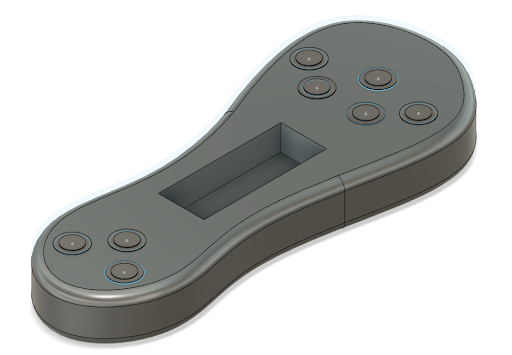


When testing prototype A, we realized that the piezoelectric sensors did not have great contact, so we decided to use a design we created to the right for better contact with the piezoelectric sensors
The next problem involved how to fit this circuit inside the shoe. We decided to integrate the PiezoModules inside the insole as shown below. The wires are wired to the middle of the insole, where we connected all the electronics, which then in turn wired into the batter on the side.


The show was created, and one of our team members tested the shoe to see how much power was generated. Each step generated around 20-35V for around 0.3 Seconds.
With prototype A we learned a few key facts. we realized that the PCB insole was too fragile, so we decided to relocate it to the side of the shoe. We then also decided to use a 35mm Piezoelectric sensor rather than a 27mm one, to have better contact from the foot and the piezoelectric crystal. Lastly, the voltage was way too high, we even broke a battery. we had to somehow convert the ~30V to ~5V for the battery to safely charge.
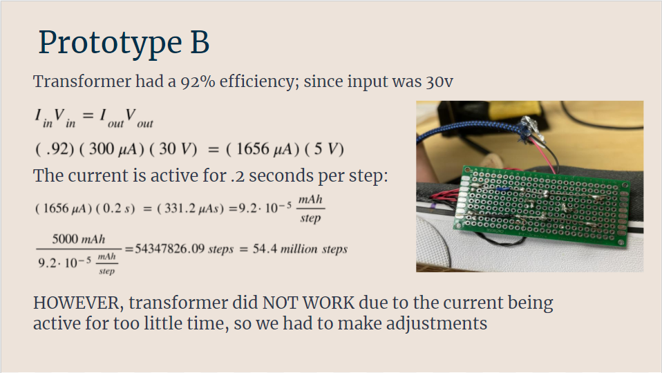
Prototype B:
Our next goal was to convert this high voltage and low current to a low voltage and a higher current. This was our next solution:
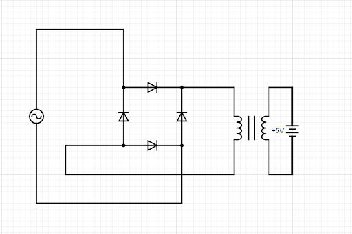

We decided to use a Step-Down converter to convert the 30V to 5V.
Prototype C
In our next prototype, we decided to use a voltage divider to mitigate the issue of high voltage.


Results:


Comments